


20
2018
History of refrigeration
In the 1800s natural refrigeration was a vibrant part of the economy. Natural ice harvested from the pristine rivers and lakes of the northern United States, particularly those in New England, was in demand. Harvested ice was stored in large quantities in ice houses and covered with sawdust for insulation.
Later, merchants loaded the ice in sailing ships as ballast. Again, the ice was covered with sawdust. Ice was delivered to as far away as India, where it was welcomed, and to England, where interest was low. The supply of harvested ice was erratic, depending on the weather where it was harvested.
During the 1800s many mechanical-type refrigeration systems were being invented and used refrigerants such as sulfur dioxide, methyl chloride, ether, carbon dioxide, as well as wine, brandy, vinegar, etc.
The early refrigeration systems designed between 1850 and 1920 produced ice year-round to compete with harvested ice. The harvested ice producers advertised that-when it was available-their natural refrigeration did not fail like the early mechanical systems.
Several approaches existed for ice manufacturing during the early days. A very labor-intensive method used a series of 10 × 14 ft* plates immersed in water with a refrigerant of ammonia or circulated brine. Ice formed on both sides of the plates. This approach provided ice without any air bubbles and used potable water. The ice was harvested with warm brine or hot gas and cut to size for sale.
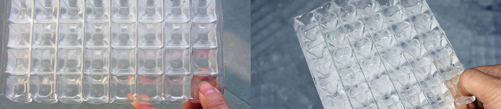
The other approach, still used today, was the can ice system. The complaint then was that it required distilled water to prevent air bubbles in the ice. This ice manufacturing method prevailed because it was simple and less labor-intensive than the plate method. As in the early days, 300 lb cans are used today to manufacture ice.
As early as the 1880s, Carré ammonia absorption systems operated in south Texas. They were used to manufacture 1,000 lb of ice per day. The absorption machine was fired with wood. According to one author, O. Anderson, this ice competed with harvested ice shipped to Texas from Boston. The machine was in Austin where two ice plants existed, one a plate ice machine and the other a can ice machine. In Chicago, a company built several plate ice machines that were shipped to the King Ranch in south Texas. These plants eventually were converted to an ice. The refrigeration system was a mechanical compressor with a steam drive.
The ice industry continued to grow, and large plants with ice capacities to ice 20 railcars at a time were installed from the Rio Grande Valley to the east coast. The plants made ice in 300 lb cans and crushed the ice before blowing it into the railcar’s bunkers. Most used steam-driven ammonia compressors. Atmospheric condensers also were appearing, as the supply of well water or river water was insufficient.
The condenser water was cooled by a spray system on the roof of the ice plant or sprayed over a pond. Gas engines and diesel engines replaced some of the steam drives as time went on and fuel prices became affordable. A number of block ice plants were installed as late as the 1950s. The last block ice plant installed in the country was in Houston during the early 1980s. It was a 100 ton/day** plant.
Some refrigeration systems installed in the early 1900s used carbon dioxide (CO2) as the refrigerant. The systems required condenser water cold enough to prevent the system from operating in the supercritical area (under 750 psig**). CO2 was available from the brewing industry at a lower cost than ammonia.
The condenser water usually came from a well or from a river. The compressors were adaptations of ammonia compressors that were modified with smaller diameter pistons to account for the much lower specific volume of CO2. Further use of CO2 occurred in the 1930s when it was used as a cascade refrigerant with ammonia as the high side to obtain low temperatures for freezing foods and to provide refrigeration for cold storages. CO2 is used in the same way today to obtain temperatures to -66°F while reducing ammonia charges and decreasing the size of the low-temperature compressors.
Ammonia absorption systems, the first systems to use ammonia as the refrigerant, still are used despite their inefficiency and high capital cost. These systems were viable into the 1950s and 1960s where waste heat, process heat or waste steam was available. This type of system was used in the very early days to obtain lower refrigerant temperatures than mechanical systems.
The classic ammonia absorption system was refined in the 1930s and 1940s to produce nearly pure ammonia. Most of these systems were installed in petrochemical or gas plants. They have been installed in the last few years in conjunction with gas turbine generating systems to satisfy government regulations. New versions of ammonia absorption systems are being designed today with much better efficiencies.
In the early 1900s, reciprocating compressors were refined. However, they still operated at low revolutions per minute. They were driven by reciprocating steam engines, which were integral with the compressor. These compressors were called open compressors, as each connecting rod had a packing to prevent ammonia from escaping. Most compressors were vertical with the steam engine horizontal. Speeds were gradually increased, and synchronous motors eventually were used instead of the steam engines. Some horizontal slow-speed ammonia compressors were built in these years. In the 1980s some of these compressors were still being operated successfully. They were motor driven with flat belts.
In the 1920s/1930s, more advances occurred in the ammonia compressor area. Most of the machines had crankcases and were considered closed compressors. The only seal involved was one on the crankshaft. These machines were more compact and generally more efficient. They were driven by synchronous motors at speeds to 360 rpm and belt-driven. Several U.S. and European manufacturers produced such machines.
During these years the cold storages and freezers used bare-pipe coils, usually 1¼ in. steel pipe, along with the walls and in bunker form on the ceilings.
Defrosting the coils was difficult in freezers as removing the ice from the rooms was strictly manual labor. The coolers’ condensate drains also were numerous. The coils fouled with oils from the compressors because oil separation systems were not perfected. This type of evaporator was still in use in the 1980s. In the late 1930s and 1940s, finned surface evaporators began to displace the bare-pipe coils. Most of the finned surface evaporators were originally water defrost. Most of the refrigeration systems still were using hand expansion valves to feed ammonia to the generally flooded evaporators. The condensers were either vertical or horizontal shell-and-tube type with spray ponds or roof spray systems to cool the condenser water.
In the late 1930s and early 1940s, new compressor development produced a v/w-type compressor that operated at rotating speeds to 1,200 rpm and in sizes from 20 to 300 hp. These machines were smaller, lighter, and less expensive than the older vertical compressors, which were discontinued by some manufacturers in the 1950s.
Slightly better oil separators also were developed. These machines have been improved engineering-wise over the years and are still viable compressors for smaller refrigeration systems. Most manufacturers of this type of compressor have ratings for all refrigerants including ammonia, halocarbons, hydrocarbons, and CO2.
For low-temperature applications, the v/w compressors performed well until refrigeration systems became larger and required increased compressor displacement. Thus, in the l940s and 1950s, the rotary air compressor was converted to refrigeration applications as a low-stage or booster compressor. These machines were fixed Vi and not very efficient, but could pump a lot of gas. The only capacity control was by varying speed.
These compressors were used for various refrigerants in low-temperature applications. Most of those applied in ammonia systems have been replaced by helical screw compressors.
In the late 1940s and even into the 1950s, automatic hot gas defrosts systems started to replace water defrost for air units in freezer applications. And the days of electric defrost and air defrost also were numbered.
The l950s and 1960s saw a major increase in the frozen food industry, which had been given its impetus when Clarence Birdseye learned how to process vegetables for freezing. Larger plants became plentiful. The refrigeration systems’ demands became larger, making the rotary compressor and the v/w compressor displacements inadequate. The huge equipment rooms and multiple compressors posed a major concern for food plant engineers. Then, use of the liquid overfeed (liquid recirculation) system came into its own. It had been patented in 1925 but rarely seen until the systems became large enough to justify its application. Evaporative condensers took the place of the shell-and-tube and cooling tower systems. The evaporative condenser had been around since the late 1930s, but its use had been limited.
In the late 1960s, the helical screw compressor, invented in Sweden in 1935, was being manufactured in several countries, but not in the U.S. A small design/build contractor brought the first ammonia screw compressor into the country and packaged it as a booster compressor. This was a major addition to the industrial refrigeration compressor field. These efficient compressors had far more displacement than the available reciprocating compressors. This compressor type was being imported by a company that was using them on R-22 air-conditioning water chillers. Helical screw compressors can be used for almost any high-pressure refrigerant.
The early screw compressor packages had relay logic controls, some of which still are operating today. Microprocessors replaced the relay logic controls in the late 1970s. Programmable controllers also are used to controlling these compressors. These controls and the many advances in screw compressor design provide excellent screw compressor control.
During the last 30 years, screw compressor designs have improved in the
following ways:
from the original handwheel slide valve (capacity reduction) adjustment to a hydraulic system,
from symmetric to asymmetric profiles for better efficiency, to roller bearing systems from sleeve bearings for better efficiency,
from fixed Vi to variable Vi to increase system efficiency,
from mesh-type oil separators to coalescing oil separators to reduce oil carryover,
to better internal designs to reduce noise, and
too much larger displacement machines to satisfy the demand for larger refrigeration systems.
In the late 1970s, a single screw compressor was introduced into the global market to compete with the twin helical screw compressor in the smaller displacement area.
Food freezing system designs have changed dramatically since Clarence Birdseye’s day. The initial freezing system was a horizontal plate device that froze vegetables in packages. The refrigerant was usually ammonia, and the units were quite small. They were great at the time but were quickly outgrown. Plate-type freezers, both horizontal and vertical still are used today to freeze vegetables and other items, such as TV dinners in packages or various commodities in bulk blocks.
In the late 1930s through the 1950s, belt freezers were used to freeze vegetables such as peas, cut corn, lima beans, etc. Most used downdraft air onto a thin layer of the vegetables. Various attempts were tried to keep the products individually quick frozen (IQF). Nearly all did not work and “cluster busters” broke up the product that often was frozen in sheets.
In the 1960s, fluidized freezing was introduced. The major difference was that the air was blown from under the belt and at a velocity that would fluidize the product (keep it in suspension).
Various methods of initiating fluidization were tried. Some worked much better than others. Later, a dual-belt system was devised. The first belt was loaded with a thin layer of product to be frozen. Most vegetable and fruit products have a thin layer of water on them when introduced into the freezer. The first belt is used to quickly freeze the thin layer of moisture when it is introduced to -20°F** air. The product is then lowered onto the fluidizing belt where it can be 6 to 10 in. deep and can be frozen in usually eight to 10 minutes, depending on the product. Many variations of IQF freezers are available today. This type of system has been applied to freezing 100,000 lb of french fries an hour.
Larger products that require longer freezing times are usually frozen on spiral freezers. This freezer usually handles such products as hamburger patties, poultry parts, pies, cakes, packaged items, etc. Several variations of spiral freezers exist, some having more than 3,000 ft of belting to provide freezing times as long as an hour.
All of these technological advancements have led to today’s efficient freezing methods for making ice and producing frozen foods.
Contacts & Support
Focusun Refrigeration CorporationRoom 603, Baohong Center
No. 7755 Zhongchun Rd
Shanghai CHINA
ZipCode: 201100
Tel: +86-21-5108 9946
Fax: +86-21-5227 2259
Email: enquiry@focusun.com
Sales: sales@focusun.com
Marketing: marketing@focusun.com
Press: press@focusun.com
Newsletter: newsletter@focusun.com
